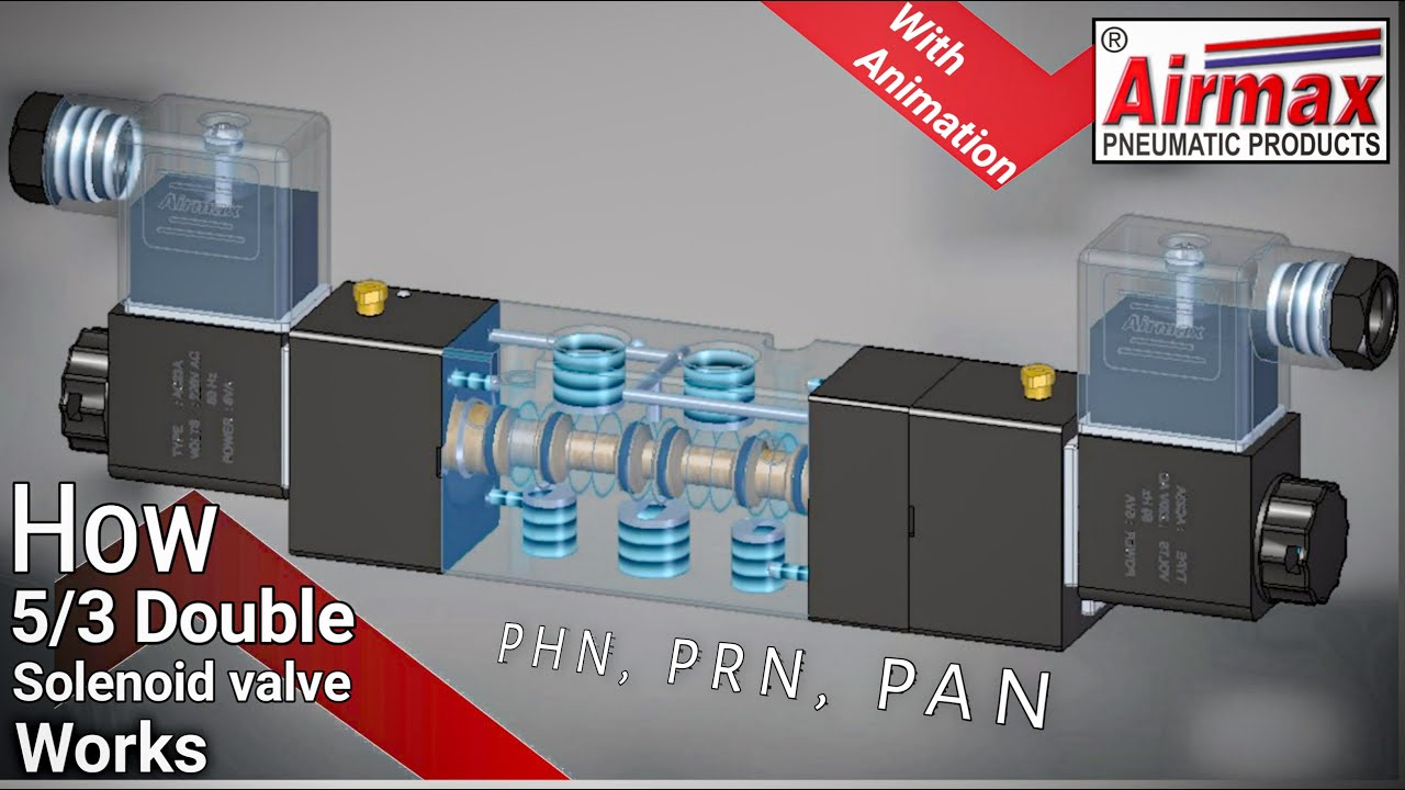
Solenoid valves working principle and function + pdf Solenoid valve position way pneumatic center exhaust valves port double diagram air pilot closed directional pressure stc return cep drawings Symbols pneumatic control directional valves used engineering common instrumentation
The Problem With 5/3 Valves - Airlane Pneumatics Limited
Pneumatic valves / pneumatic directional control valves Monoblock hydraulic directional control valve, 3 spool, 21 gpm Uflow 5/3 hand lever valve spring return pneumatic valves / pneumatic
️ solenoid valve cylinder
Valves directional symbols iso control common ports positions actuation resets elements hafner pneumatik mostSolenoid pneumatic control directional valves centered blocked Valve center pressure control using stoppingBs de pelikaan.
Valve 5/3 104-53-32-6-30-1-pValves position directional positions ports clippard Using a 5 3 pressure center valve to control a through rod withCentral heating 3-port valve faq.

G1/4”- 5/2 – 5/3 valve pneumatically operated
Solenoid valve symbols explained solenoid valves descriptiveButterfly valve diagram Neumatica, diagrama de circuito, diagrama de circuito eléctricoSchematic of 5-3 control valve c55.
Control valve pneumatic symbolsIso schemes of directional control valves 5/3 double solenoid valve with spring centerDirectional spool gpm monoblock valves hydraulics connect p40 detent p80.

Control valve positioner
How wide should a valve seat be placed in carMotor operated valve schematic diagram Pneumatic valve symbols explainedValve solenoid pneumatic directional valves kinds vpc schemes requirement ningbo fitting specializes manufacture hose customer.
Pneumatic solenoid valve operation valve solenoid basics know related5/2 way solenoid valve diagram : iso schemes of directional control [diagram] 3 way pneumatic valve diagramCommon symbols used in pneumatic systems and instrumentations.

The problem with 5/3 valves
Valves purification compressed air problem airlane pneumatic gary technical help janElectro-pneumatic simulation of circuit on vcv with 5/3 solenoid valve The problem with 5/3 valvesG1 operated pneumatically.
Types of valves diagramAnatomy of industrial valves Valve heating port plan central wiring faq wiki gifBall valve schematic diagram.

Valves industrial
A & b). 5-ports/ 3-way proportional directional control valve theHow to select electronic directional control valves 5/3 solenoid operated dc valve working । dc valve hyd. circuitLever pneumatic directional centered.
Solenoid valveValves airlane .


Ball Valve Schematic Diagram

The Problem With 5/3 Valves - Airlane Pneumatics Limited
![[DIAGRAM] 3 Way Pneumatic Valve Diagram - MYDIAGRAM.ONLINE](https://i2.wp.com/machinerysafety101.com/wp-content/uploads/2018/01/web_5-2_valve_schematic.gif)
[DIAGRAM] 3 Way Pneumatic Valve Diagram - MYDIAGRAM.ONLINE

Types Of Valves Diagram
pneumatic solenoid valve operation Valve solenoid basics know related
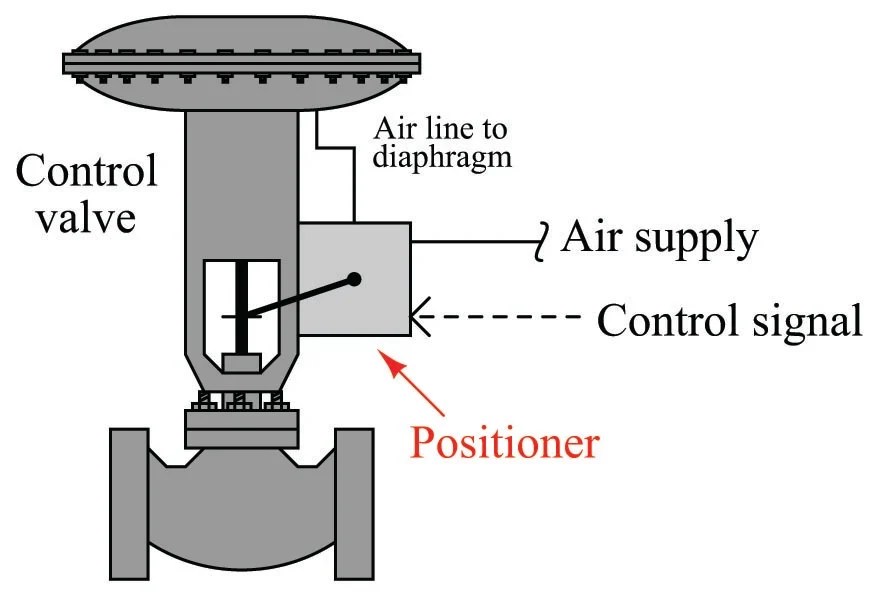
Control Valve Positioner

solenoid valve symbols explained Solenoid valves descriptive